Back to projects

DriveWire mini EV telemetry platform

A real bench-build in progress: ESP32-S3 firmware, dual DC motor drive, battery and current telemetry, a front-mounted distance sensor, CAD fixtures, and a protected custom PCB power path taking shape in Altium.

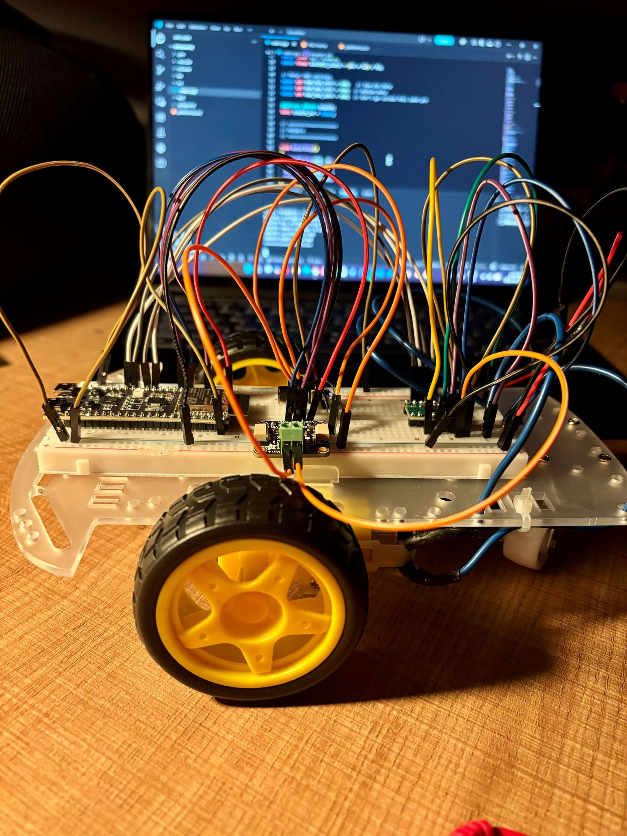
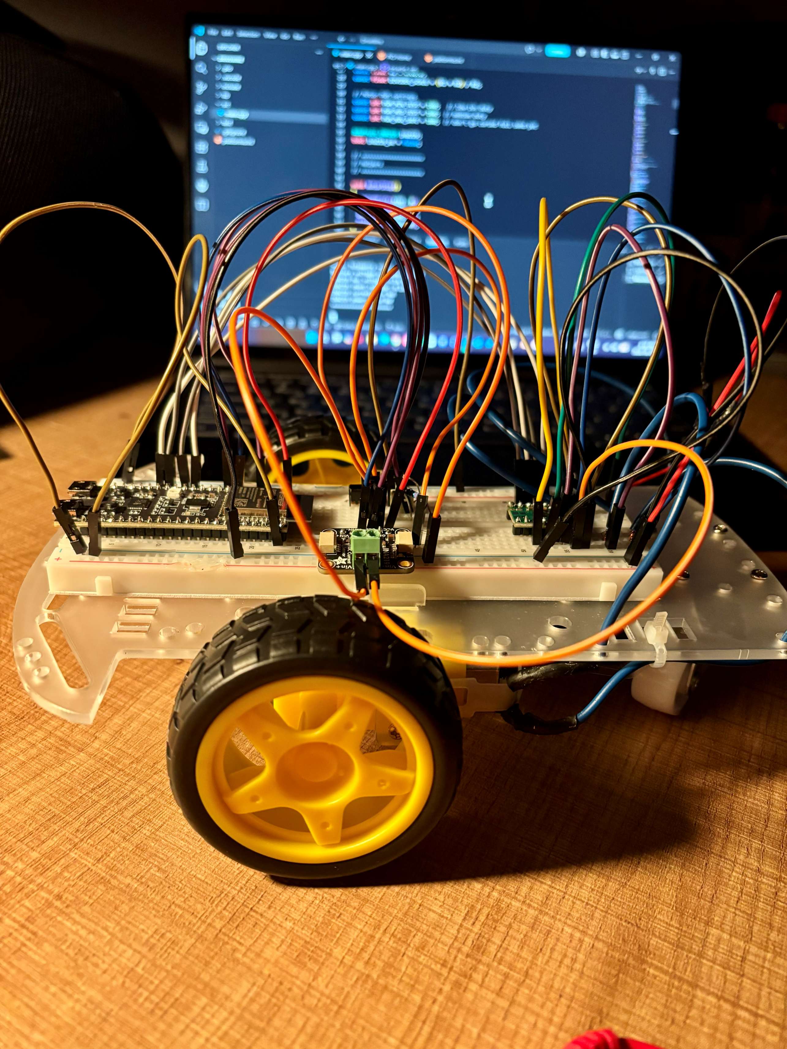
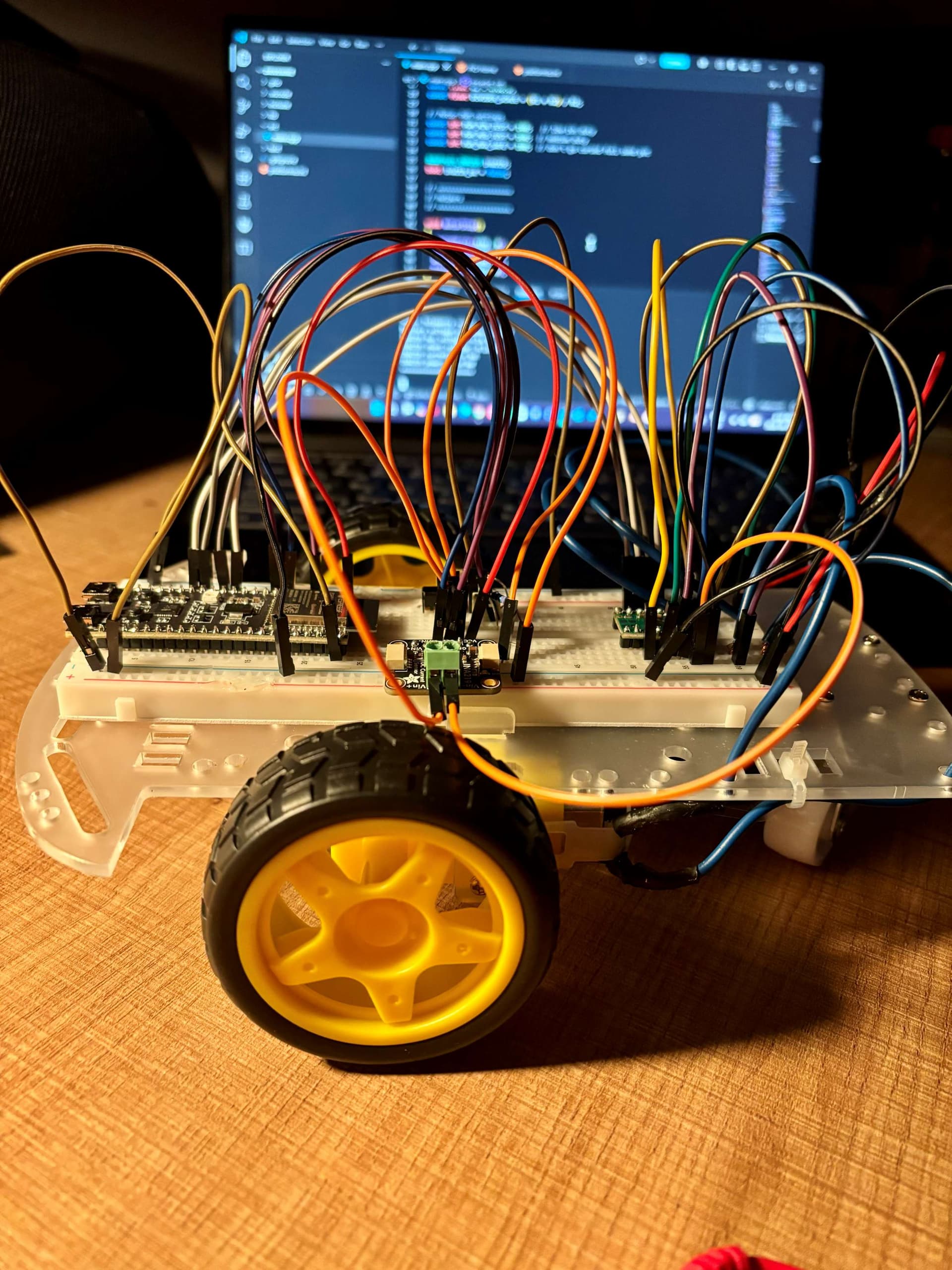
DriveWire bench prototype wired on a chassis in front of firmware code
Current phaseSensor + PCB integration
ControllerESP32-S3
Drive2WD DC chassis
Next milestoneToF firmware
Bench replay · Jul 14 sessionidleBUS 5.73 VCURRENT 2.8 mAPOWER 16 mW
Build state

A system brought up on the bench.

What exists today

DriveWire has moved from parts collection into physical integration. The motor terminals are soldered, both wheels run on the printed test stand, battery and current telemetry flow over serial, and the VL53L1X distance sensor is wired and mounted at the front of the chassis.

Swap-based debugging isolated a failed motor-driver channel and brought both wheels online using two working channels. Forward and reverse are confirmed; left and right behavior is documented in a command truth table and still needs a mapping and polarity correction. In parallel, the first custom PCB battery power schematic is now underway in Altium.

Bench test

Debugging video showing the two-driver workaround and both wheels spinning on the printed support stand.

Architecture

One controller, one power path, visible telemetry.

How the system hangs together

An ESP32-S3 sits at the center. Firmware serial commands drive a DRV8833 dual H-bridge, which powers the two DC gear motors. Power flows from the AA pack through a switch and the INA219 current sensor, so the firmware can watch bus voltage, current, and power while a divider feeds battery voltage straight into the ESP32's ADC.

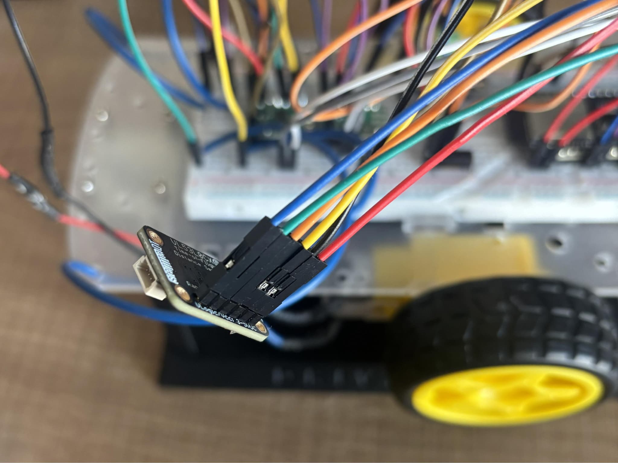
A VL53L1X time-of-flight sensor is now wired and mounted at the front of the chassis. Firmware bring-up is next, beginning with I2C ranging and obstacle detection. The same telemetry loop remains the foundation for the Wi-Fi command and dashboard layer that follows.

System diagram

DriveWire system architectureBlock diagram showing the AA battery pack feeding a switch, INA219 current sensor, and DRV8833 H-bridge driving two motors, with an ESP32-S3 controlling PWM, reading I2C telemetry and USB serial commands, plus mounted ToF sensing and a planned Wi-Fi dashboard.POWER PATHAA batterypackSwitchINA219shuntDRV8833H-bridgeMotor LMotor RESP32-S3firmware + telemetryUSB serialbring-upVL53L1X ToFmountedWi-Fi dashboardplannedPWMI2C

Serial bring-up today · VL53L1X mounted · custom power schematic underway

Power design

The custom PCB starts with a protected power path.

Battery entry architecture

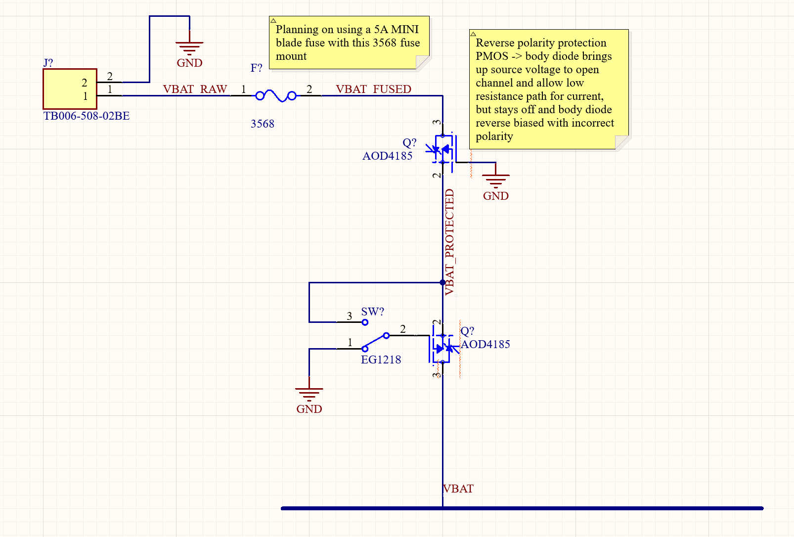
The first Altium schematic moves DriveWire toward cleaner vehicle electronics. Battery power enters through a screw terminal and planned 5 A MINI blade fuse before reaching two AOD4185 PMOS stages.

01

Fuse protection limits major short-circuit current at the battery input.

02

A reverse-connected PMOS blocks current if the battery polarity is wrong.

03

A second PMOS carries the load while the 200 mA slide switch only controls its gate bias.

04

ESP32-controlled shutdown is being evaluated before the V1 schematic is frozen.

Battery power schematic

Altium schematic showing the DriveWire battery input fuse, reverse-polarity PMOS, and PMOS-controlled main power switch
Battery input protection and switching · July 20
Engineering stories

Debugging that actually happened.

Fault isolation

The dead motor channel

Symptom

During dual-motor bring-up, one wheel ran cleanly while the other stayed dead.

Hypothesis

The fault could live in the firmware pin mapping, the wiring, or one output channel of the DRV8833 driver itself.

Test

Swapped the driver's inputs and outputs so each suspect carried the other's signal, and watched whether the dead behavior followed the wiring or stayed with the driver output.

Fix

The fault stayed with one driver output. That channel was retired, and the second wheel now runs on the working channel of a backup driver, so both wheels spin.

Learned

Swap-based isolation pins a fault to a single stage quickly, without special equipment. The follow-up turn investigation found left and right simply swapped in the mapping, so the fix is a firmware logic flip.
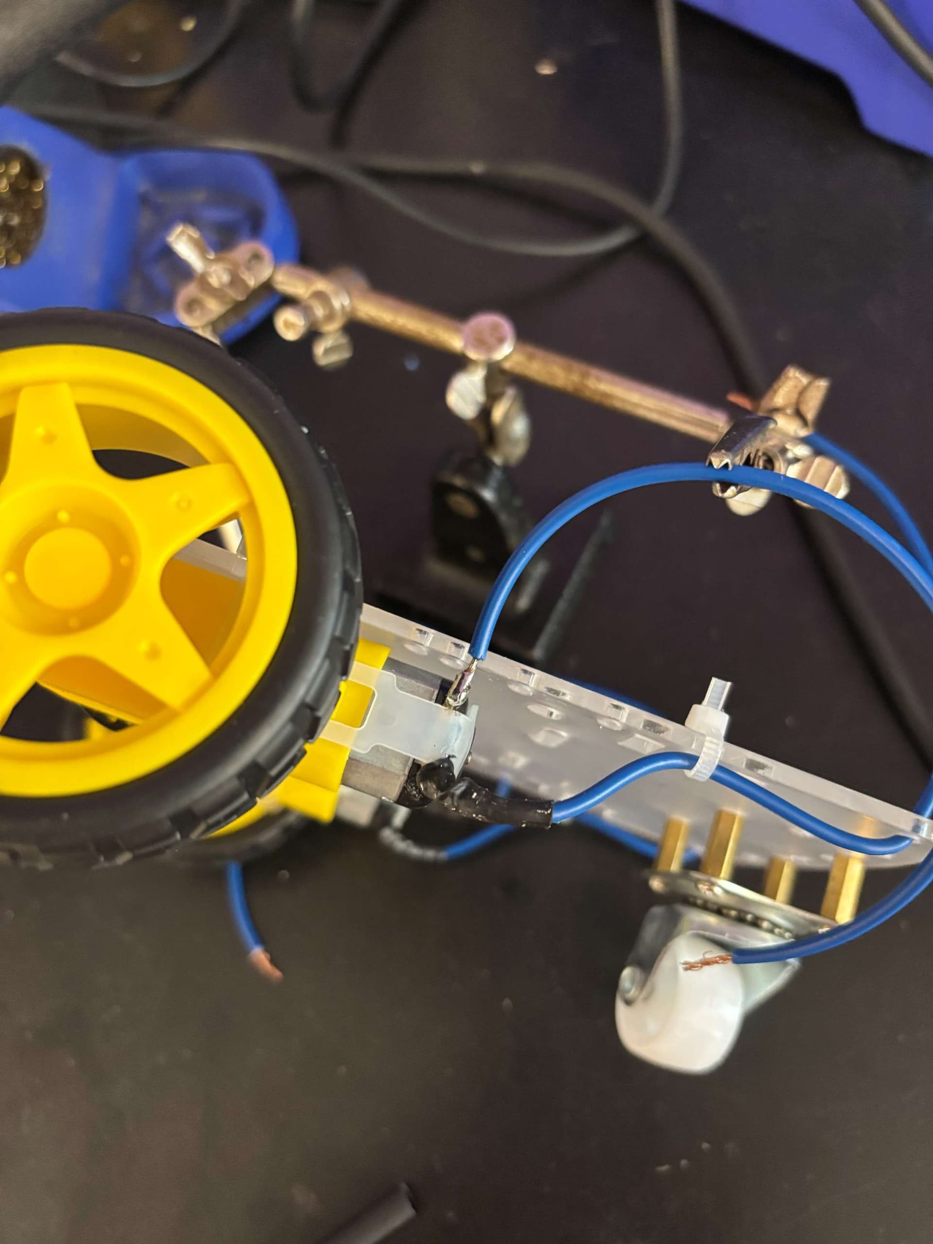
Motor terminal wiring with soldered automotive wire and heat shrink
Motor wiring under test
PWM threshold

Motors that hum but do not move

Symptom

At low PWM duty values the motors drew power and hummed, but the wheels never turned.

Hypothesis

The commanded duty produced too little torque to overcome the gearbox's static friction.

Test

Raised the duty value through firmware pulse tests until the wheels broke free consistently.

Fix

Set 140 as the working duty floor, so drive commands launch from a value the drivetrain can actually act on.

Learned

Real actuators are nonlinear at the low end. Firmware has to respect a minimum-duty threshold instead of assuming torque scales smoothly from zero.

DriveWire chassis wired on the bench in front of firmware code
Bench wiring during PWM tuning
Test fixture

A test stand instead of a runaway robot

Problem

Bench-testing drive commands with the chassis on a desk was unsafe and unrepeatable: the wheels needed to spin freely without the vehicle going anywhere.

Approach

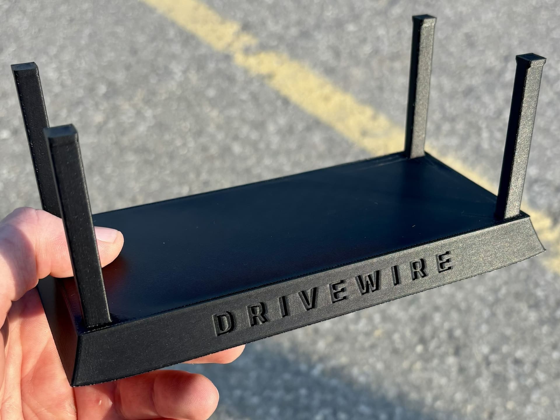
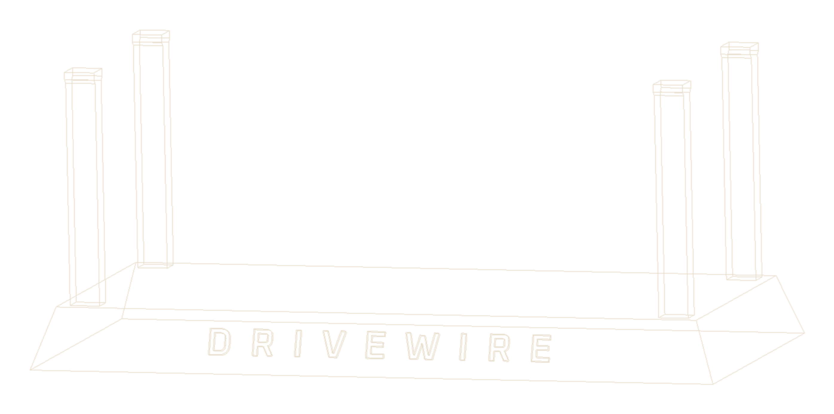
Modeled a custom support stand in SolidWorks to hold the chassis with the wheels suspended, iterated the support geometry, and printed it in black PLA on a Raise3D E2.

Iteration

A printer error stopped the first print early. The second attempt reached late-stage progress with slight corner lift, noted for brim and bed-temperature tuning.

Result

The finished stand holds the chassis securely with the wheels free to spin. It has been the stable testbench used for every motor debugging session since.

Learned

Test fixtures are part of the engineering. A repeatable bench setup made every debugging pass after it faster and safer.

Finished black PLA DriveWire support stand with engraved front lettering
Final print on the bench
Wireframe render of the custom DriveWire support stand CAD model with engraved lettering
Custom DriveWire support stand · SolidWorks
Roadmap

Speed with direction.

01

Working now

  • Chassis on printed test stand
  • Both wheels spinning
  • Battery and current telemetry
02

In progress

  • VL53L1X firmware bring-up
  • Turn-command mapping correction
  • INA219 validation
03

Next up

  • Complete custom PCB schematic
  • Wi-Fi control interface
  • Live dashboard telemetry
04

Later V2

  • Custom PCB layout and bring-up
  • Upgraded battery pack
  • Camera / autonomy
Firmware

Bring-up code that talks to real hardware.

Current firmware signals

01

Serial command menu for bring-up

02

Motor A / Motor B pulse tests

03

Forward, reverse, left, right, coast, and brake commands

04

Battery voltage divider read through ESP32 ADC

05

INA219 bus voltage, shunt voltage, current, and power reads

06

Telemetry print loop while the vehicle is under test

t = print telemetry
a = pulse Motor A
b = pulse Motor B
p = pulse both motors
f/r = forward/reverse
s/k = coast/brake

Telemetry:
Battery voltage estimate
INA219 bus voltage
INA219 current
INA219 power
Records

The paper trail.

Dated build log10 entries · June 12 – July 23
June 12

Mechanical chassis assembled

Built the 2WD chassis with DC motors, wheels, front caster, and wheel encoder discs to create the rolling test platform.

June 13

ESP32-S3 communication confirmed

Brought up the microcontroller over serial and confirmed the board could communicate cleanly with the development machine.

June 14

Motor driver soldered and direction tested

Soldered the DRV8833 motor driver board, wired an initial powertrain circuit, and confirmed motor forward/reverse behavior from firmware.

June 29

Full bench circuit wired and PWM issue debugged

Soldered motor leads, heat-shrunk joints, mounted the battery pack and breadboard, added current and ToF sensor boards, and solved a low-PWM static-friction issue by raising the duty value to 140.

July 1-3

SolidWorks support stand designed for testing

Modeled a custom DriveWire stand, iterated support geometry, sliced the STL, and started a black PLA print on a Raise3D E2 so the wheels can spin safely during bench tests.

July 6

Support stand print restarted and adhesion issue noted

A printer error stopped the first stand print early, so the job was restarted. The second attempt reached late-stage progress, with slight corner lift noted for future brim, bed-temperature, or first-layer tuning.

July 7

Printed stand became the DriveWire testbench

Picked up the successful black PLA support stand and confirmed the chassis mounts securely and remains stable, creating a safer bench setup for motor debugging and firmware bring-up.

July 8

Motor driver fault isolated and both wheels brought online

Swapped motor driver inputs and outputs to isolate the dead channel, confirmed the fault stayed with one driver output, then used the working channel on a backup driver so both wheels spin. The active bug is now turn-command direction mapping.

July 20

Custom PCB battery power architecture started in Altium

Designed the first battery-entry schematic for the custom DriveWire PCB, including a planned 5 A fuse, AOD4185 PMOS reverse-polarity protection, and a second PMOS so a low-current slide switch can control the main power rail safely.

July 23

VL53L1X distance sensor wired and mounted

Wired the time-of-flight sensor and secured it at the front of the chassis for forward obstacle detection. The next step is firmware bring-up, followed by a purpose-built printed mounting bracket.

V1 bill of materials8 items in use
01

ESP32-S3 DevKitC-1-N8R8 main controller

02

Pololu DRV8833 dual motor driver under active test

03

2WD robot chassis with wired DC gear motors

04

AA battery pack for motor power during V1 bench tests

05

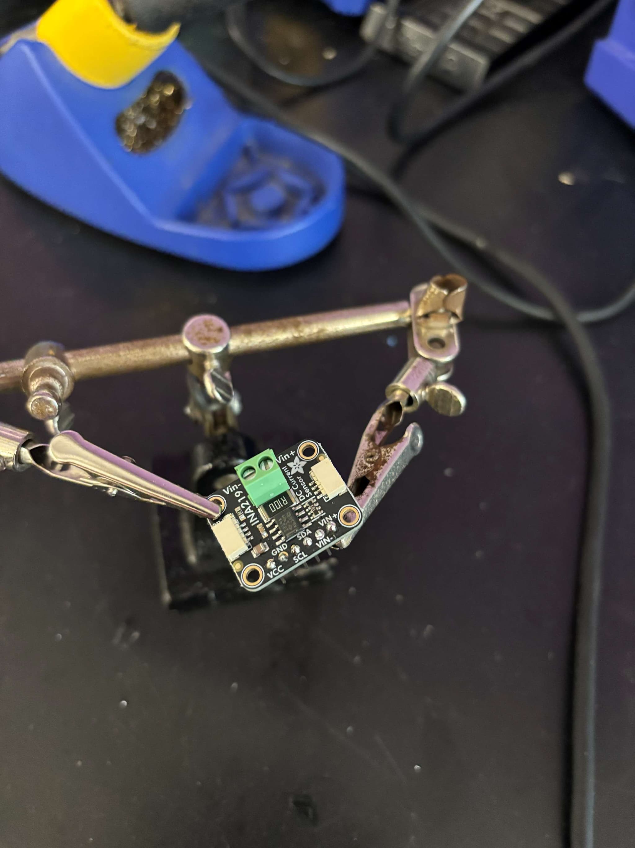
INA219 current sensor soldered for current and power measurement

06

VL53L1X distance sensor wired and mounted for forward obstacle detection

07

22 AWG automotive wire, heat shrink, zip ties, and mounted breadboard

08

SolidWorks support stand printed in black PLA for safer debugging

Next

DriveWire is moving.

Both wheels run on the printed stand, forward and reverse commands work, and battery and current telemetry flow over serial. The VL53L1X distance sensor is mounted for firmware bring-up, while the custom PCB now has a protected battery input architecture in Altium. The immediate work is ranging, turn-command correction, current validation, and completing the PCB schematic before Wi-Fi control and live dashboard telemetry.