Back to projects
Formula Electric AILED safety board
A ground-up redesign of Waterloo Formula Electric's accumulator indicator LED board, owned end to end: requirements, architecture, component selection, schematic capture, PCB layout, and validation. The circuit must detect high-voltage presence directly and produce an isolated 12 V indicator output with no software in the loop.
Problem
Make the voltage indicator legal without depending on normal LV power.
Why this matters
The Accumulator Indicator LED is a hard-wired safety signal that must illuminate whenever high voltage is present at the accumulator bus, including when the vehicle's normal low-voltage supply is unavailable. The challenge is therefore more than simply driving an LED; the circuit must detect high-voltage presence, generate its own isolated low-voltage power, and operate reliably without software or external control.
I am designing the new AILED board from scratch. The work starts with translating the Formula Student rules into electrical requirements, then defining the sensing and isolated-power architecture, selecting components, and carrying my own design through schematic capture, PCB layout, and validation. The legacy board and the related TSAL DCDC serve as context only: the vehicle's interfaces are treated as fixed constraints, and everything between them is a clean sheet built around hard-wired behaviour, strict HV/LV isolation, and rules-compliant creepage and clearance.
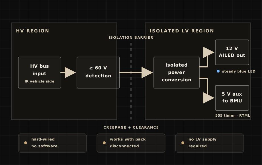
The result will be a compact, standalone safety circuit that produces an isolated 12 V output whenever the required high-voltage threshold is reached, regardless of the vehicle's low-voltage state.
Concept architecture
Two outputs: steady 12 V for the indicator, 5 V aux for the BMU timer
Design drivers
What the board has to prove.
HV-driven indicator
The blue accumulator indicator has to turn on from high-voltage bus presence, even when the pack is disconnected from the car or no normal low-voltage supply is available.
Isolated low-voltage output
The design target is an isolated 12 V output for the indicator connector whenever the high-voltage bus reaches the required threshold.
No software dependency
The indicator path has to be direct hard-wired electronics. It cannot depend on firmware, software state, or the signal that closes the isolation relays.
Auxiliary 5 V path preserved
The board keeps a second output: an auxiliary 5 V rail feeding the BMU's 555 timer circuit that flashes the ready-to-move light. The AILED indicator output itself stays steady rather than pulsed.
Rules
Constraints shaping the schematic.
Each tractive battery pack needs a prominent indicator when high voltage is present at the vehicle side of the isolation relays.
The voltage indicator must function even when the tractive battery pack is disconnected or removed.
High-voltage presence must directly control and power the indicator through hard-wired electronics with no software control.
The control signal that closes the isolation relays must not control the voltage indicator.
Current work
Design path.
Define the HV threshold, indicator output, auxiliary rail, and isolation requirements before committing to the circuit architecture.
Design the HV-triggered isolated supply path that can produce the 12 V indicator output without relying on normal LV power.
Reference the previous AILED and related TSAL DCDC work only as context for interfaces, constraints, and lessons learned.
Preserve the auxiliary 5 V output while keeping the indicator behavior steady.
Validate high-voltage / low-voltage spacing, isolation boundaries, and creepage constraints before layout release.
Next
Active design work.
The AILED board is early enough to show the real engineering problem without pretending the design is finished. More schematic, layout, and validation evidence can be added as the board matures.